As mentioned elsewhere, we bought a new 24Ve last fall and started to modify it for ballasting early this spring. We finally launched it in late June and have been so busy having fun and learning to wakesurf (with lots of family and friends) that I never wrote up what we did.
Duffy's writeup thread set the standard, so I'm going to follow in his footsteps and add sections over a period of time.
A quick note of thanks to everyone here who chimed in with answers and suggestions when I asked questions. A special thanks goes to ChpThril, who is always willing to share his extensive knowledge. An extra special thanks must go to Jason at WakeMakers, who tolerated numerous phone calls and emails as I came up with crazy/insane ideas and needed a sounding board; he was always willing to overnight fat sac fittings and components to me on short notice. Another extra special thanks to Harvey Smith at Tige in Abilene, who also tolerated calls and emails about the 24Ve's design and provided engineering drawings and other technical data that proved invaluable.
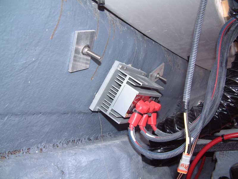
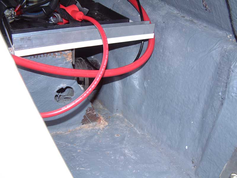
A while back, I mentioned that I wanted a designated tow point for inflatables. My 24Ve didn't come with one, but others had asked Tige's grab handle fabricator to build one with an integrated tow point. This requires an extra two holes in the transom to accommodate the bolts the come off the towing eye. When I looked at cutting those two holes, I found that the battery isolator had been mounted centered and directly behind the grab handle:
Thus to install the integrated handle/towring, I'd have to relocate the battery isolator. Initially, I planned to mount the isolator on a piece of Starboard that was epoxied to the transom:
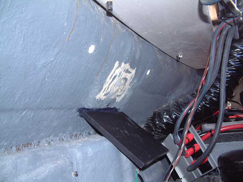
However, as I started focusing on the ballast system, I realized that if I were going to concentrate the ballast as far rearward as possible - and maximize its volume - I would be modifying the entire transom area and engine compartment. I decided to make the isolator part of that overall redesign, and the Starboard came back off the transom.
The 24Ve's rear storage lockers use carpeted walls to create a "rectangular" space. Behind this space hides the batteries, TAPS pump, etc. Below the floor hides either the factory hard ballast tanks or foam blocks to support the floor.
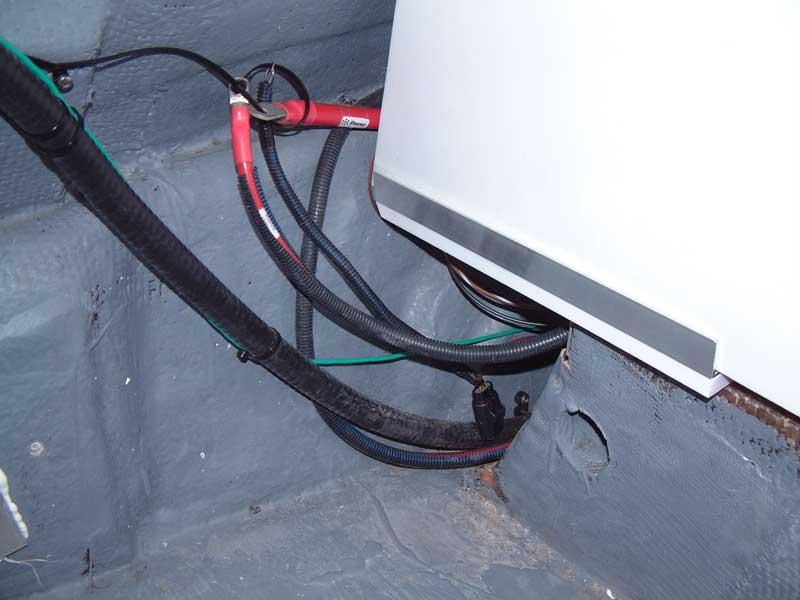
That's a LOT of wasted space, right where you want to concentrate your ballast. For example, here's a shot of the port side factory rear locker wall (after I had added a second battery switch for the house battery):

If that wall and everything behind it could be removed, and the floor and everything beneath THAT removed, the ballast could extend all the way to the transom itself. But where to relocate the batteries, TAPS pump, battery isolator, etc.?
Many people relocate their batteries forward, under the side seat cushions. But this is counterproductive because those batteries have a lot of lead (read: weight) in them and the whole point of ballasting is to put weight in the rear of the boat.
There is, however, a nice big open space available in the rear of the boat... right behind the engine (this photo skips ahead a bit with respect to the removal of the locker walls, locker floors, and foam support blocks but I'll cover that in a later installment):
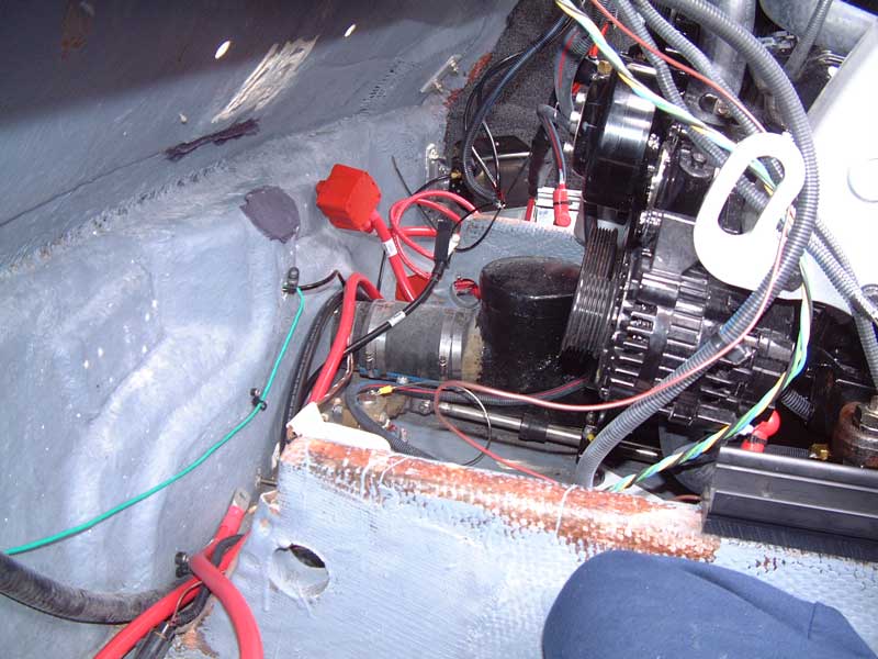
This photo looks a little confused, but the fact is that there is a lot of space there. Importantly, the engine stringers (which by definition are very strong) run right back to this area. If some method could be found to rotate the corner contents (batteries, TAPS pump, etc.) back behind the engine, we could use this space productively and open up all that corner volume for massive amounts of completely hidden ballast.
The two engine stringers form a planar surface that could accommodate a shelf-like structure. Then, looking to the left of the lower stringer in the photograph, you can see where the blower originally mounted to the transom. Tige glasses in some extra material there so the blower can be screwed to the transom. There are similar mounting surfaces in several other locations across the transom. Instead of the original components, these surfaces could be mount points for shelf supports. A properly cut and shaped shelf could be used to hold everything that needs to move out of the corners.
The two big concerns here are clearance to the front of the engine with its moving parts, and temperature since the engine will heat this space to around 160F. The former is a matter of careful design and placement. The latter really isn't much different than the original factory layout, since all the components already shared a common airspace with the engine.
To get started, I cut some pieces of 1.5 inch stainless angle. One was used to act as a primary shelf support, transferring the weight of the batteries to the engine stringers. The others were used as transom supports for the rear edge of the shelf:
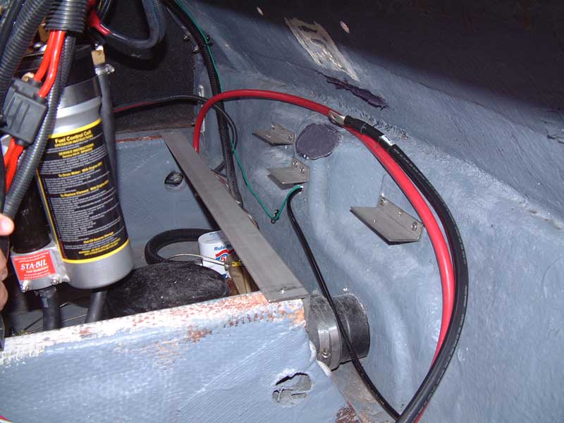
Using its transom mount for the shelf obviously meant the blower had to move. Federal regulations require that the blower's intake be in the lower 1/3rd of the lowest compartment in which fuel vapors may congregate. Measurements showed that mounting the blower directly through the shelf, such that its intake was in the space under the shelf, satisfied this requirement.
Next, I built a prototype shelf out of some scrap particle board:
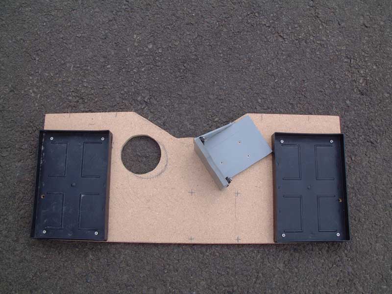
The factory battery trays and TAPS mounting plate were relocated to this shelf. A hole was cut for the blower, and a template sketched for approximate isolator location.
Once the details were worked out, a final shelf was cut from a piece of Starboard:
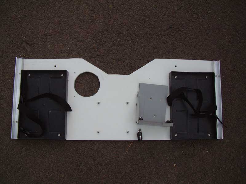
The battery straps are now in place, a clamp has been added to control battery cable routing, and holes have been tapped to accommodate the isolator. The aluminum channels on either side are there to hold the bottom edge of new, additional engine divider walls to support the fat sacs on either side.
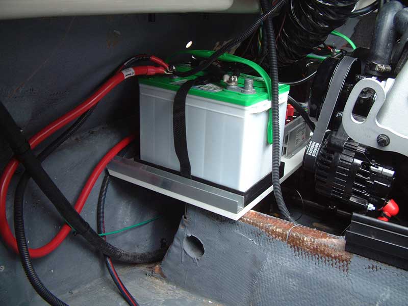
When the shelf and all components were installed, the result looked like this from the starboard side:
...and from the port side:
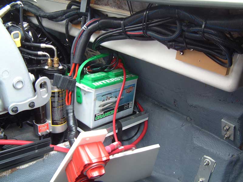
This latter photo shows one of the new engine divider walls that rest in the aluminum channels on the battery shelf. The two battery switches have been moved to this new wall since the original locker rear wall is gone.
Here are shots of the ballast space on either side of the new battery shelf. The new starboard engine divider wall is in place (wires and such have not yet been dressed out in these photos):
Note that the absolute rear and bottom of the hull is now visible. Custom fat sacs can be built to fill this ENTIRE volume, which is much larger than the standard 24Ve locker. More about those in a later installment.
More soon... thanks!
Duffy's writeup thread set the standard, so I'm going to follow in his footsteps and add sections over a period of time.
A quick note of thanks to everyone here who chimed in with answers and suggestions when I asked questions. A special thanks goes to ChpThril, who is always willing to share his extensive knowledge. An extra special thanks must go to Jason at WakeMakers, who tolerated numerous phone calls and emails as I came up with crazy/insane ideas and needed a sounding board; he was always willing to overnight fat sac fittings and components to me on short notice. Another extra special thanks to Harvey Smith at Tige in Abilene, who also tolerated calls and emails about the 24Ve's design and provided engineering drawings and other technical data that proved invaluable.
A while back, I mentioned that I wanted a designated tow point for inflatables. My 24Ve didn't come with one, but others had asked Tige's grab handle fabricator to build one with an integrated tow point. This requires an extra two holes in the transom to accommodate the bolts the come off the towing eye. When I looked at cutting those two holes, I found that the battery isolator had been mounted centered and directly behind the grab handle:
Thus to install the integrated handle/towring, I'd have to relocate the battery isolator. Initially, I planned to mount the isolator on a piece of Starboard that was epoxied to the transom:
However, as I started focusing on the ballast system, I realized that if I were going to concentrate the ballast as far rearward as possible - and maximize its volume - I would be modifying the entire transom area and engine compartment. I decided to make the isolator part of that overall redesign, and the Starboard came back off the transom.
The 24Ve's rear storage lockers use carpeted walls to create a "rectangular" space. Behind this space hides the batteries, TAPS pump, etc. Below the floor hides either the factory hard ballast tanks or foam blocks to support the floor.
That's a LOT of wasted space, right where you want to concentrate your ballast. For example, here's a shot of the port side factory rear locker wall (after I had added a second battery switch for the house battery):
If that wall and everything behind it could be removed, and the floor and everything beneath THAT removed, the ballast could extend all the way to the transom itself. But where to relocate the batteries, TAPS pump, battery isolator, etc.?
Many people relocate their batteries forward, under the side seat cushions. But this is counterproductive because those batteries have a lot of lead (read: weight) in them and the whole point of ballasting is to put weight in the rear of the boat.
There is, however, a nice big open space available in the rear of the boat... right behind the engine (this photo skips ahead a bit with respect to the removal of the locker walls, locker floors, and foam support blocks but I'll cover that in a later installment):
This photo looks a little confused, but the fact is that there is a lot of space there. Importantly, the engine stringers (which by definition are very strong) run right back to this area. If some method could be found to rotate the corner contents (batteries, TAPS pump, etc.) back behind the engine, we could use this space productively and open up all that corner volume for massive amounts of completely hidden ballast.
The two engine stringers form a planar surface that could accommodate a shelf-like structure. Then, looking to the left of the lower stringer in the photograph, you can see where the blower originally mounted to the transom. Tige glasses in some extra material there so the blower can be screwed to the transom. There are similar mounting surfaces in several other locations across the transom. Instead of the original components, these surfaces could be mount points for shelf supports. A properly cut and shaped shelf could be used to hold everything that needs to move out of the corners.
The two big concerns here are clearance to the front of the engine with its moving parts, and temperature since the engine will heat this space to around 160F. The former is a matter of careful design and placement. The latter really isn't much different than the original factory layout, since all the components already shared a common airspace with the engine.
To get started, I cut some pieces of 1.5 inch stainless angle. One was used to act as a primary shelf support, transferring the weight of the batteries to the engine stringers. The others were used as transom supports for the rear edge of the shelf:
Using its transom mount for the shelf obviously meant the blower had to move. Federal regulations require that the blower's intake be in the lower 1/3rd of the lowest compartment in which fuel vapors may congregate. Measurements showed that mounting the blower directly through the shelf, such that its intake was in the space under the shelf, satisfied this requirement.
Next, I built a prototype shelf out of some scrap particle board:
The factory battery trays and TAPS mounting plate were relocated to this shelf. A hole was cut for the blower, and a template sketched for approximate isolator location.
Once the details were worked out, a final shelf was cut from a piece of Starboard:
The battery straps are now in place, a clamp has been added to control battery cable routing, and holes have been tapped to accommodate the isolator. The aluminum channels on either side are there to hold the bottom edge of new, additional engine divider walls to support the fat sacs on either side.
When the shelf and all components were installed, the result looked like this from the starboard side:
...and from the port side:
This latter photo shows one of the new engine divider walls that rest in the aluminum channels on the battery shelf. The two battery switches have been moved to this new wall since the original locker rear wall is gone.
Here are shots of the ballast space on either side of the new battery shelf. The new starboard engine divider wall is in place (wires and such have not yet been dressed out in these photos):
Note that the absolute rear and bottom of the hull is now visible. Custom fat sacs can be built to fill this ENTIRE volume, which is much larger than the standard 24Ve locker. More about those in a later installment.
More soon... thanks!


Comment